GWE (Gas-Water-Energy) logger
Energy logger
Goals:
1. Can we see how much electric power is used by compliancies without plug (for instance light bulbs)?
2. Is it possible to see remote if lights are turned off?
This is a rather old idea. The basic idea was from around 2000, when I gave the assignement to a group students to design this for me. They did not design a solution but stayed in reporting possible solutions, so the idea was put on the pile with ideas. Until the summer of 2016 when some friends seems to have the same idea.
Due to the fact that I still got a Arduino-Mega laying around after the 3D printer project I decided to use that as the controller. And after our main fuses were replaced and extended with more groups, beginning of 2016. I decided to measure the power per group.
Step 1: measure the current per group
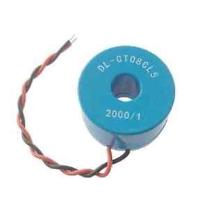
- The current is easy measured with a current transformer. There are many transformers available. But in my case I would like to have one that fits in the casing of the main fuses, can handle 16A, and has a high isolation value and no sharp metal connections that can damage the isolation wires of the existing wiring. So I ended up with: CT08CL5 which costs a bit more than 1 euro.
- We want to measure small power as well as full-power, so the first ideas was to have either a) switchable gain amplifier, b) non-linear gain amplifier, or c) multiple amplifiers with ADCs. For simplicity I started with just a non-switchable amplifier to see if all this extra complexity is really needed. So the current is transferred to a voltage by a simple IV converter. Which was later replaced by just a resistor.
- For optimal use of the ADC we want to use the full-range of the ADC; resulting in the max resolution.
- Due to the fact that the current can be negative and positive, while the (chosen) ADC can not handle the negative values the voltage over the resistor needs to be shifted so that the minimal voltage will be 0V. So the voltage to shift the measured value needs to be half the full-range of the ADC. If the ADC max value is equal to Vref, it means we need to shift the measured voltage with Vref/2.
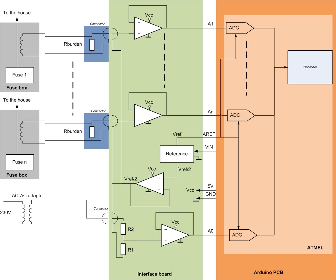
- A short browse on internet showed that I was not the first to design an electric power logger: https://openenergymonitor.org/emon/buildingblocks/ct-sensors-interface. From that webpage I took the simple schematic which is the implementation of the text above (see below).

- With the following changes:
- The R1, R2 are not placed, but the mid-point is connected to Vref/2 (see next section)
- In my case the Rburden needed to be 220E, because: Burden Resistor (ohms) = (AREF * CT TURNS) / (2√2 * max primary current)
- The input resistance of the ADC inside the arduino is too low ohmic to connect it directly to the burden resistor, so I added a buffer opamp (see section buffer opamp).
- The burden resistor is put inside the connector on the current transformer side, such that when the current transformers is not connected to the buffer the voltage over the current transformer will always be kept low (no flash-overs can occur). For this reason I needed connectors in which I can place a resistor easily. So I chose mini-jacks.
Step2: Measure the voltage
There is no need to measure the voltage per group, but due to the time spend in measuring one group the voltage has a different phase during the measurement of the other groups. This could easily be solved by remeasuring the mains voltage at the same time as the current.
The design of the circuit to measure the voltage is similar as the current measurement circuit.
- A short browse on internet showed that I was not the first to design an electric power logger: https://openenergymonitor.org/emon/buildingblocks/measuring-voltage-with-an-acac-power-adapter. From that webpage I took the simple schematic which is the implementation of the text above (see below).
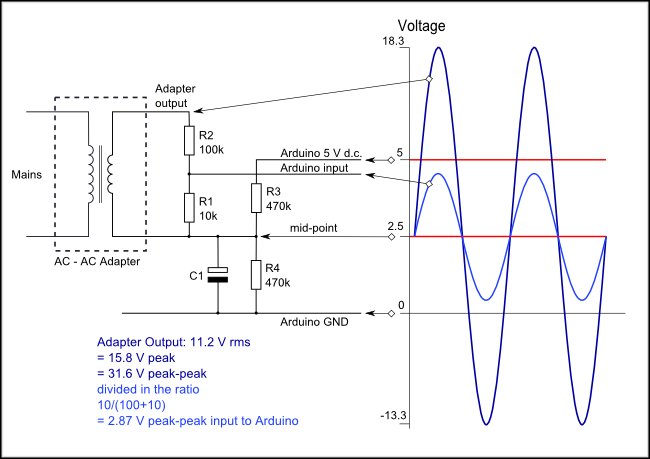
- With the following changes:
- The R3, R4 are not placed, but the mid-point is connected to Vref/2 (see next section)
- In my case the I wanted to keep the load on the AC-AC adapter as low as possible such that the phase shift of the adapter is minimal. So resistors values high.
- The output of my AC-AC adapter laying around was such that I ended up with R1=120kOhm, R2=1.5MOhm.
- The input resistance of the ADC inside the arduino is too low ohmic to connect it directly to the burden resistor, so I added a buffer opamp (see section buffer opamp).
Step 3: ADC + Reference voltage
First impression was that the ADC of the arduino was very sensitive for the used power supply. A short investigation of the arduino datasheet showed that this is cause by the fact that default the ADC ref is the 5V power supply. For this reason an external reference is added.
I have chosen to use the AD584 also due to the fact that it has a Vref/2 (unbuffered) output available. Note that this reference requires a higher power supply than 5V. But in principle the Arduino board also requires a higher input voltage to create the 5V internal, so that voltage can be used.
At first high accurate ADCs were ordered, but for simplicity of the design I have chose to start with using the 10 bit ADCs available in the Arduino Mega. I needed 10 current measurement and 1 voltage measurement, so 11 ADC inputs, which are available on the Arduino Mega, so not a problem.
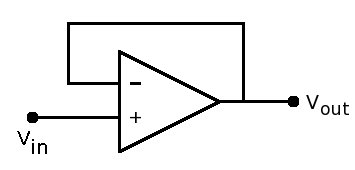
Step 4: Buffer opamp
There were two reasons to add a buffer opamp between the current transformer and the ADC:
- The ADC is rather low-ohmic and will cause a measurement error
- When Vref is turned off the arduino gets a negative voltage on its ADC and this ADC will be damaged. By using the same power supply for the reference as for the buffer opamps this is automatically safe.
The buffer opamps for the current coil can be in principle any opamp that is available, but there are some things to consider:
- If we use 5V as supply aswell as for Vref we should use a rail-to-rail opamp to be able to use full range of the ADC
- The bias and the offset current will give a direct error in the measurements. If you want to measure below 1W it means the current error should stay below 1W/230V = 4.3mA. With a gain of 2000 => 2.2uA. So the bias current and offset should stay well below that value.
- The voltage offset will give via the burder resistor also a measurement error. In my case the burden resistor was 220E so that means the offset voltage should be well below 220E*2.2uA = 0.48mV. Note that item 2 and 3 are directly related. So if one is just meeting the spec the other should be well below such that it can be neglected.
- The opamp is powered allways (assuming the energy logger is always logging) so a low power consuming opamp is also wise to pick.
The buffer opamps for the voltage measurement have similar considerations.
The buffer opamps for the reference have also similar considerations but in that case the voltage offset will result in a direct reference error and require some extra attention.
Step 5: Calculating the power
To calculate the power used you need the current, voltage and the phase difference between them.
Luckily more people are working on this, so in my case I just downloaded the arduino libraries:
https://github.com/openenergymonitor/EmonLib
Step 6: Logging
First I started with logging on a local SD card. To be able to do so I needed to know the time. A standard example of getting real time in Arduino is available in the examples, so that could be easy added.
Secondly I would like to have a readout of the values remote (all over the world). For this I used:
because they had examples of Arduino available and was easy to implement.
Future idea is to use the Arduino also a web-host, but that has not been implemented.
Step 7: Power usage of the logger itself
Because the logger is always logging its power usage is also interesting.
The Arduino Mega board (assuming you use the local regulator) requires at least 6.6V. And the external reference also requires something like 7V. For this reason a 7.5V adapter is used.
| Component |
Current used (mA) |
| Arduino Mega |
51 |
| Ethernet shield + SD card |
157 |
| Buffer opamps |
13 |
| Reference |
1 |
Using an old stable regulator the total power used was around 4W. By using a newer switch-mode AC-DC converter the power usage dropped to around 2.5W, which was acceptable for this application.
The main consumer is the Ethernet shield.
Step 8: Cost of the logger
| Component |
Price [Euro] |
Type |
Link |
| Arduino Mega + Ethernet/SD shield |
11.11 |
Mega2560 |
AliExpress |
| 10 current transformers |
14.10 |
CT08CL5 |
Ebay |
| SD card |
5.95 |
|
Action |
| 6 opamps |
2.83 |
For example:
TLC2272
|
Many types available, for example:
AliExpress
|
| 7.5 power supply |
9.99 |
|
kijkshop |
| Connectors (div.) |
1.90 |
|
<diverse> |
| Accurate reference |
2.69 |
AD584 |
AliExpress |
| TOTAL |
48.57 |
|
- |
AC-AC adapter, resistors and PCB were available from old electronics; and thus not mentioned in table above.
Step 9: Pictures of the setup
Installation of the current transformers
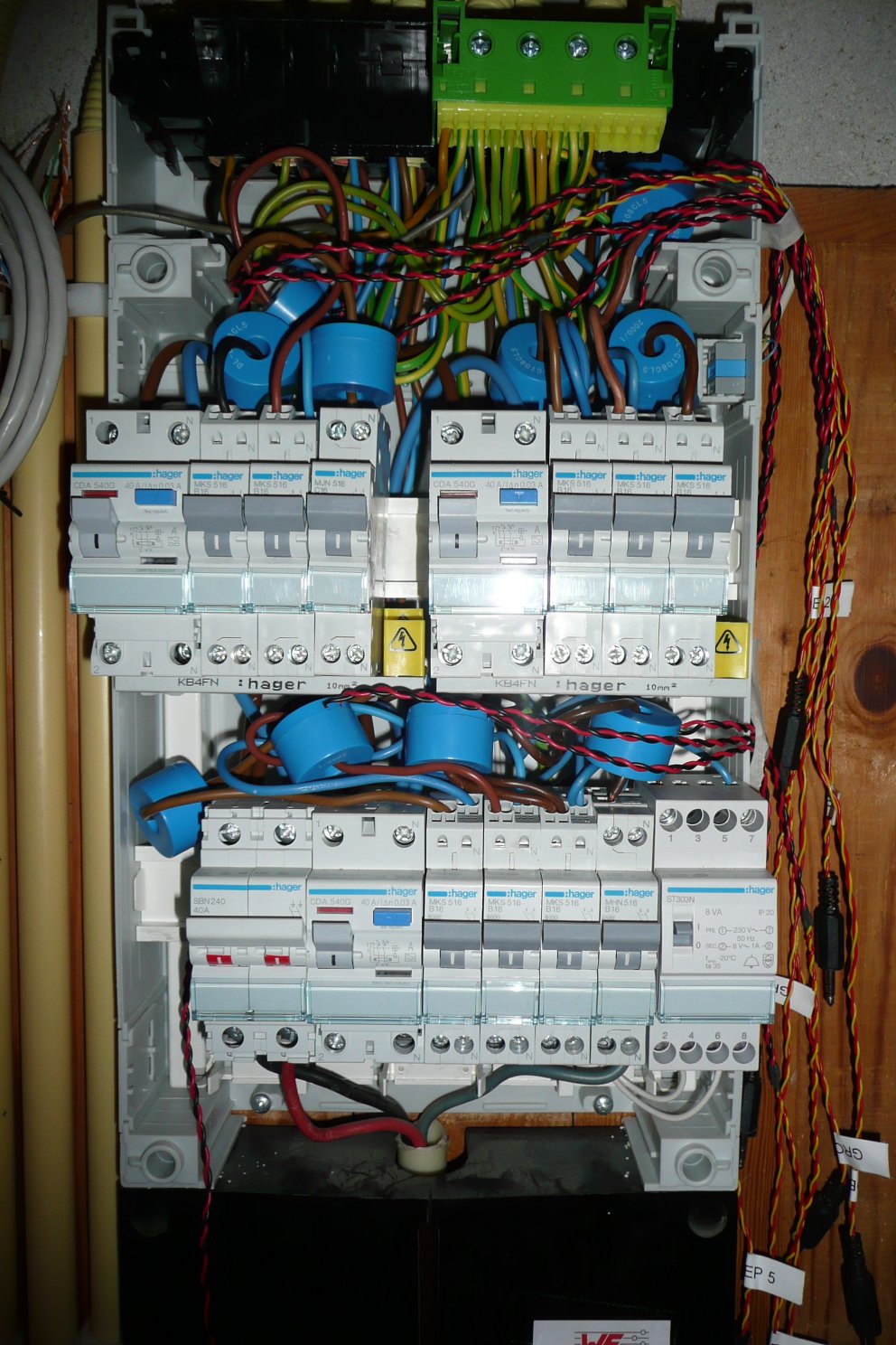
And the electronic (buffers + Arduino)
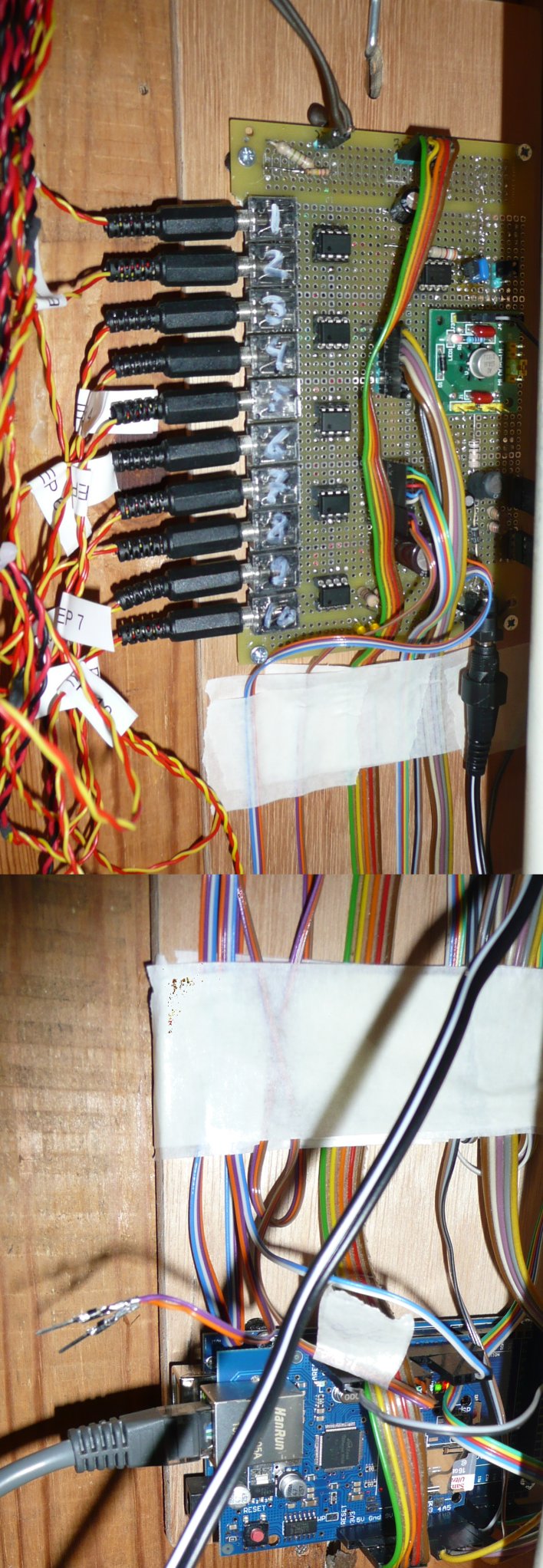
Due to the fact that the Arduino and the AC-DC power supply disturb the low analog signals they are replaced further away (see band cables in photo above).
Step 10: Circuit diagram
Mapping of the circuit above on the photo of the interface board (for n = 10):

Extra in this figure are some small components (R, C, Diodes) that are used for filtering of the supply.
Also some LEDs were added to diagnose errors of the Arduino; also not in the circuit diagram.
Step : Accuracy of the readout
The accuracy is determined by:
- Phase shifts
- The phase shift due to measuring current and voltage at different moments (there is a certain time already passed)
- Phase shift due to the used voltage readback method (transformer), which is slightly loaded by the resistors
- Phase shift due to current readout by a transformer
- Current readout error
- The current to voltage transformation done via a regular resistor => can be up to 10%, due to the choses accuracy of the resistors. Is a fixed value so could be calibrated.
- Due to used opamps:
- Error is introduced due to the bias current of the buffer opamps
- Error is introduced due to the voltage offset of the buffer opamps
- Reference voltage
- Mismatch between the Vref and Vref/2
- Accuracy of the Vref
- Stability of the Vref (due to supression of the Vcc variations)
- Accuracy of the Arduino ADC is limited to 10 bits
- Voltage readout error
- The resistive voltage divider => can be up to 2*10%, due to the choses accuracy of the resistors. Is a fixed value so could be calibrated.
- Due to used opamps:
- Error is introduced due to the bias current of the buffer opamps
- Error is introduced due to the voltage offset of the buffer opamps
- Reference voltage
- Mismatch between the Vref and Vref/2
- Accuracy of the Vref
- Stability of the Vref (due to supression of the Vcc variations)
- Accuracy of the Arduino ADC is limited to 10 bits
Lets look in more detail to the accuracy of 10 bits:
- The circuit above uses a 220E resistor. A current flowing through this resistor can allow in a voltage of maximal 2.5V (Vref/2). So that means that its maximal current is 2.5V/220E*2000 = 22.7A-peak (16A-rms in case of sinus). The smallest detectable current step is then equal to 22.7/2^9 = 44 mA-peak (31mA-rms in case of sinus).
- voltage......
- averaging.....

Water logger
Now that the electricity logger is installed (see above) it is easy to add things. The first addition was the water logger. The water meter has a small "moon" at the lowest digit which can easily be monitored either visual or via an inductive proximity sensors. Each time the moon rotates a puls is generated. This puls is handled in the Arduino code via an interrupt, so that no pulses are missed.
The output voltage of the inductive prox sensor is just above 5V (equal to the supply of the sensor), so two resistors are added as a voltage divider.

Such a proximity switch can be bought for circa 2.50 euro.
Connection of the sensor is done via an easy wood piece connected with tie-raps around the meter (see photo above).
Gas logger
In the "6" of the last digits of the gas meter is a small mirror.
Via a cheap IR detector + LED (circa 0.30 euro incl. PCB and comperator) the passing of this "6" can be detected.
Only "problem" is the aligning of the sensor for exactly the mirror.
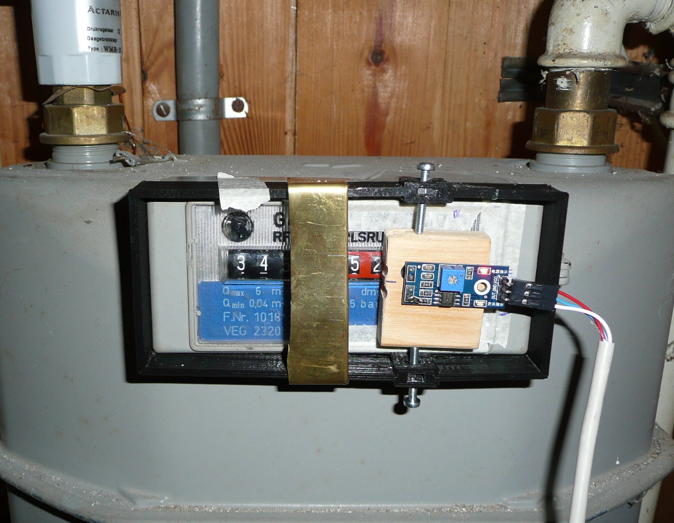
We designed a small black bracket (see photo) around the gas-meter so it is easy to remove sensor when needed.
End 2017 the gas-meter is replaced by a "smart-meter" gas meter. The previous gas-meter was no longer "allowed".
With this "smart"-gas meter an automatic readout can be done via the electricity meter. See section "smart-meter".
Smart meter
There is of-course nothing smart to this meter. But it has a so called P1 interface.