LGB Train
Goal: Automate LGB train tracks

Steps:
- Make a control centre
- Convert old battery locomotive to regular locomotive
- Convert manual "wissels" to remote controlled
- Create a loc decoder to allow multiple locs on the track
- Add loc sounds
- Make it possible to add a loop to a track
1. Make a control center
Goal: create a DDC control unit.
REPLACE WORDS WITH RIGHT TERMINOLOGY: Command station, Throttle, etc
Protocol LGB: NMRA "DCC" standard
https://www.nmra.org/index-nmra-standards-and-recommended-practices
Assuming the max voltage of +/- 22V of DDC (source), requires a step-down converter able to withstand 44V input (minus de drop over de rectifier).
Basics:
Issue:
- If you use a L298 motor bridge, keep in mind that this bridge for using bidirectional control has usec delays between two outputs. This will cause "stair-case" output signals instead of nice pulses.
- Open issue: why is the "switching direction" needed? It is just a block wave, without any reference. Only disadvantage: you need to double your power supply voltage.
- For example: one rail on +12V DC, while the other rail is switching between 0V and +24V --> delta between the two tracks is between -12V and +12V.
Testing and understanding data:
- Using the Saleae Logic analyzer + DCC protocol plugin
- Be carefull signal is much too high for this logic analyzer. So make sure you measure behind an optocoupler of resistor divider.
- Resulting in:
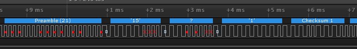
Explanation of bits:
- Starting with a PreAmble of at least xxx "1"'s
- B1: Followed by one data-byte of 8 bits, of which 1st bit (MSB) is "headlights" for old trains. Next 7 bits form the address. In the figure above this is 0000.1111; Thus address 15
- B2: Next byte (when using the DCC++) is 0011.1111 which means "128 speed steps"
- B3: Next byte is then the speed + direction. First bit (MSB) is the direction. A 1 = forward, 0 = backwards. The next 7 bits indicate the speed-1. Because emergy break is 0000.0001, you are loosing 1 speed step.
- Next byte is the checksum. The checksum is calculated by using an EXOR B1+B2+B3. So an EXOR means if sum of that bit is even answer is 0, if it is odd answer is a 1.
Note: the red crosses. Here is the timing not within DCC specs
1.1 Making a control center / 'throtle'
Step 2: creating a user controller
- Creating an input device. Arduino Mega with inputs switches and potentiometer => output serial to Arduino Uno
1.2 Making a basic DCC receiver circuit
DCC track voltage
"Without causing you great headaches, here are the maximum track voltages for the four scale settings DCC is designed for:"
| Scale |
Volts |
| Z |
11(*) |
| N |
12 |
| HO |
15 |
| O/G |
20 |
(source: https://dccwiki.com/Power_supply, with the exception of (*) which is from https://sites.google.com/site/markgurries/home/technical-discussions/boosters/nmra-track-voltages)
Frequency, rise times and fall time
While I could not find anything in the standard refering to rise times and fall time specifications. There is a hint in the https://www.nmra.org/sites/default/files/s-9.3.2_2012_12_10.pdf. It tells two things:
- 250 kbit/sec
- The risetime should be less than 0.5 usec for a voltage going from 10% of its max to 90% of its max
Starting point: http://www.mynabay.com/dcc_monitor/
On this website the following schematics can be found, in orange my corrections. Schematic components explained below the figure.
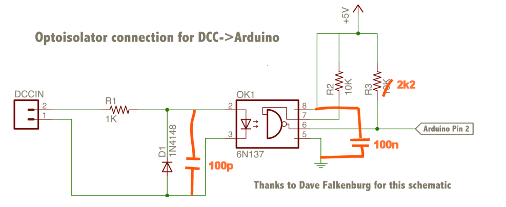
Rationale behind components and its values:
- OK1: an opto isolator will create a save separation from the higher voltage on the track and the 5V (or 3V3) of the processor. By using on the second side onlyl the VCC of the process no damage can occur to processor inputs (like pin 2 of the Arduino). By chosing a fast optocoupler like the 6N137 pulses in the MHz range can be transfered to the processor. A typical rise time of 10% -> 90% with the right loads (RL = 350 Ω, CL = 15 pF) can be 23 nsec, which is more than fast enough. Maybe even too fast. And the fall time can be even faster (RL = 350 Ω, CL = 15 pF) typical 7 nsec.
- R1: The maximal voltage on the track is 20V. The maximal current through the optocoupler is 20mA. The voltage drop over the input of the optocoupler is about 1.4V. So R1 should be minimal (20V-1.4V)/20mA = 930 Ohm if you want to make it a generic circuit. If you decide to use a different track voltage you can lower your resisance, just replace the 20V in previous equation with your track voltage.
- D1: The optocoupler only works in one direction. So current should only flow in that direction. If current flows in the other direction it takes a while before it can switch to its normal direction. This is called recovery time. So the optocoupler recovers slowly from a reserse voltage making it in some cases too slow to measure either rising or falling side of the pulse. By puting a parallel fast diode like the 1N4148 it will not recover too slow.
- C1 (not in figure): Because we have now created a fast circuit all noise and distrurbances on the track should be filtered out to make sure it is not seen as a pulse by the Arduino. Rough estimate: everything with a frequency component above the a few MHz should be filtered out. Keep in mind that there is an input capacitances of the optocoupler (Cio~50pF) and a small capacitance of the diode D1 (Cd~5pF), these are both in addition to this C1. To meet the requirement of 10%-90% within 0.5usec, the total C (so including Cd of diode D1 and Cio of the input of the optocoupler) should be below 227pF (2.2*R*C < 0.5sec https://en.wikipedia.org/wiki/RC_time_constant). So advise is to add a capacitor C1 in the range of 50 pF - 150 pF. Note: during the addition of 100pF in 40% of the cases it was not enough to surpress a small spike. In those cases a 300pF had to be added iso 100pF.
- R2: exact value no reason (????)
- R3: Determines the rise time of the signal. By having a high value the rise time will take along time, causing the pulse to be seen as not a real DCC signal. In principe the R3 determines the rise time of the DCC signal. When applying C1 there is no direct need to use R3 for filter working, but we should make sure the R3 is not chosen such that the rise-times are no longer compliant to the DCC standard. Pin 6 "sees" a capacitance due to a) the output of the optocoupler (Coo~15pF), b) wiring/traces (Cw~5pF), and c) the input capacitance of pin 2 Ca~20pF. Which totals Cx~40pF (**). The rise time can be estimated by 2.2*R3*Cx (2.2 Tau, https://en.wikipedia.org/wiki/RC_time_constant). So with a Cx of 40pF and a required rise time of less than 0.5usec it means that R3<0.5u/(2.2*Cx)=5.5 kOhm. Note that the fall time with this circuit will be fast enough (and will even be too fast so filter by adding C1 is really required). Based on my own measurements (see (**)) I would advise to make sure R3 is maximal 2.2kOhm.
Secondly the maximal current through the optcoupler is 50mA so with a voltage supply of +5V during results in a minimal resistor of R3>100 Ohm.
So R3 should have a value (much) larger than 100 Ohm and max 2.2kOhm. So I would advise to pick a value in the range 1kOhm....2.2kOhm.
(**) My measurements of the rise time show that in the circuit I used the total capacitance of this Cx is about 100pF, which is about a factor of 2 larger.
- C8 (not in figure): it is also very much advised to add a decoupling capacitance as close as possible to the optocoupler from Vcc to gnd of about 100nF. Copied text from datasheet: "The use of a 0.1 μF bypass capacitor connected between pin 5 and 8 is recommended"
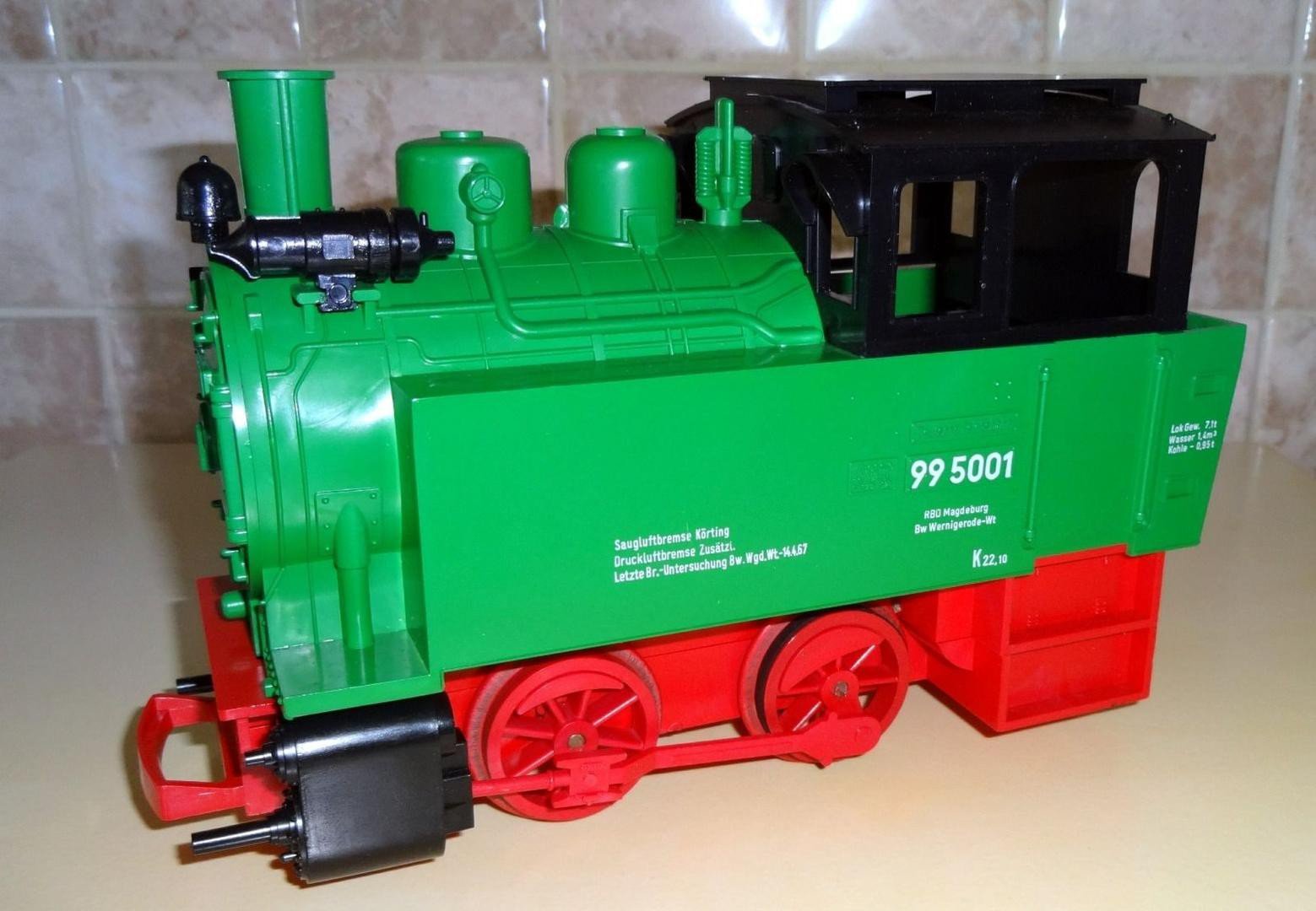
2. Convert old battery locomotive to regular electric locomotive
The start point was my old green battery LGB loc 99 5001. The plastic tracks were sold some time ago and this train was waiting for a make over to run on the regular electric tracks.
This means 2 things:
1. There needs to be a electrical signal pickup from the track
2. The voltage picked up from the track can be much too high. Remember it was a battery operated train, which means the motor was designed for ~3V DC. So a conversion is needed from the 12V...20V track to 3V.
Starting point:
=> Parked unsuccesfull !
3. Convering electrical LGB loc to DCC++
=> DONE, Working (explaining text pending)
4. Create a loc decoder to allow multiple locs on the track
=> DONE, Working (explaining text pending)
5. Convert manual "wissels" to remote controlled
=> DONE, Working (explaining text pending)
Thingiverse used part: https://www.thingiverse.com/thing:846677
Note that address byte starts always with "10" for accessory decoder.
Command for DCC++ starts with <a ...
6. Add loc sounds
6.1 Steam-whistle
Option 1: with MP3 player
Option 2: with ISD1820
6.2 Steam-engine
Based on White-noise generator:
https://www.eeweb.com/extreme-circuits/simple-white-noise-generator
7. Make it possible to add a loop to a track
8. Smoke out of loc
Started with example:
https://www.instructables.com/id/An-Inexpensive-Smoke-Fog-Generator/
9. Sounds to train station
=> DONE, Working (explaining text pending)
10. Full operational crossing (light, sound, movements)